How to choose the correct quick connect couplers size?

There are three factors in determining what Hydraulic Quick Connect Couplers are right for you.
- Body style
- Body size
- Thread size.
These three questions below are everything you need to identify the correct hydraulic quick connect couplers you're looking for.

How to Identify Thread Sizes

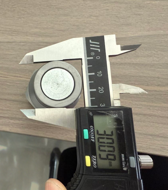
The first step to identify thread sizes of your components is measuring the diameter. You will need a caliper to do this. If you are measuring the male half of the coupling (external thread) make sure you use the bottom clamps of the caliper, and if you are measuring the female half of the coupling (internal thread) use the top clamps of the caliper to get the right measure.
These measurements will be part of the data you need to match with the information in the selection charts, but keep in mind that your measurement may not give you the exact number appearing on the chart. This can because of manufacturing tolerance or wear, but do not worry, usually the difference is minimal and you just have to choose the closest number from the selection chart.
Popular threads found in the most common fittings
National Pipe Thread (NPT):
The special characteristic of this style of thread that is going to help you identify it is the presence of an inverted 30° seat in the female half and an 30° internal chamfer in the male half.
|
Inch size
|
Dash size | Threads per Inch | Male Thread O.D. (in) | Female thread I.D (in) | ||
| 1⁄8 | -2 | 27 | 13⁄32 | 0.41 | 3⁄8 | 0.38 |
| 1⁄4 | -4 | 18 | 17⁄32 | 0.54 | 1⁄2 | 0.49 |
| 3⁄8 | -6 | 14 | 11⁄16 | 0.68 | 5⁄8 | 0.63 |
| 1⁄2 | -8 | 14 | 27⁄32 | 0.84 | 25⁄32 | 0.77 |
| 3⁄4 | -12 | 14 | 1 1⁄16 | 1.05 | 1 | 0.98 |
| 1 | -16 | 11 1⁄2 | 1 5⁄16 | 1.32 | 1 1⁄4 | 1.24 |
| 1 1⁄4 | -20 | 11 1⁄2 | 1 21⁄32 | 1.66 | 1 19⁄32 | 1.58 |
| 1 1⁄2 | -24 | 11 1⁄2 | 1 29⁄32 | 1.90 | 1 13⁄16 | 1.82 |
| 2 | -32 | 11 1⁄2 | 2 3⁄8 | 2.38 | 2 5⁄16 | 2.30 |
SAE Straight Thread O-Ring (ORB):
These are the SAE J1926-1 and ISO 11296-1 styles which also conform to MS16142, UN/UNF threads which are recommended for medium and high pressure hydraulic systems. Here, the characteristics to identify are the presence of an o-ring on the male half and a small chamfer to accept the o-ring on the female half.

|
Inch size
|
Dash size | Thread Size | Male Thread O.D. (in) | Female thread I.D (in) | ||
| 1⁄8 | -2 | 5⁄16 – 24 | 5⁄16 | 0.31 | 9⁄32 | 0.27 |
| 3⁄16 | -3 | 3⁄8 – 24 | 3⁄8 | 0.38 | 11⁄32 | 0.34 |
| 1⁄4 | -4 | 7⁄16 – 20 | 7⁄16 | 0.44 | 13⁄32 | 0.39 |
| 5⁄16 | -5 | 1⁄2 – 20 | 1⁄2 | 0.50 | 15⁄32 | 0.45 |
| 3⁄8 | -6 | 9⁄16 – 18 | 9⁄16 | 0.56 | 17⁄32 | 0.51 |
| 1⁄2 | -8 | 3⁄4 – 16 | 3⁄4 | 0.75 | 11⁄16 | 0.69 |
| 5⁄8 | -10 | 7⁄8 – 14 | 7⁄8 | 0.88 | 13⁄16 | 0.81 |
| 3⁄4 | -12 | 1 1⁄16 – 12 | 1 1⁄16 | 1.06 | 1 | 0.98 |
| 7⁄8 | -14 | 1 3⁄16 – 12 | 1 3⁄16 | 1.19 | 1 1⁄8 | 1.10 |
| 1 | -16 | 1 5⁄16 – 12 | 1 5⁄16 | 1.31 | 1 1⁄4 | 1.23 |
| 1 1⁄4 | -20 | 1 5⁄8 – 12 | 1 5⁄8 | 1.63 | 1 9⁄16 | 1.54 |
| 1 1⁄2 | -24 | 1 7⁄8 – 12 | 1 7⁄8 | 1.88 | 1 13⁄16 | 1.79 |
| 2 | -32 | 2 1⁄2 – 12 | 2 1⁄2 | 2.50 | 2 7⁄16 | 2.42 |
JIC 37° Flare or SAE J514:
This is a style commonly found in fluid power systems. The special characteristic to identify it is the presence of a 37° flared seat in both the male and female halves.

| Inch size | Dash size | Thread Size | Male Thread O.D. (in) | Female thread I.D (in) | ||
| 1⁄8 | -2 | 5⁄16 – 24 | 5⁄16 | 0.31 | 9⁄32 | 0.27 |
| 3⁄16 | -3 | 3⁄8 – 24 | 3⁄8 | 0.38 | 11⁄32 | 0.34 |
| 1⁄4 | -4 | 7⁄16 – 20 | 7⁄16 | 0.44 | 13⁄32 | 0.39 |
| 5⁄16 | -5 | 1⁄2 – 20 | 1⁄2 | 0.50 | 15⁄32 | 0.45 |
| 3⁄8 | -6 | 9⁄16 – 18 | 9⁄16 | 0.56 | 17⁄32 | 0.51 |
| 1⁄2 | -8 | 3⁄4 – 16 | 3⁄4 | 0.75 | 11⁄16 | 0.69 |
| 5⁄8 | -10 | 7⁄8 – 14 | 7⁄8 | 0.88 | 13⁄16 | 0.81 |
| 3⁄4 | -12 | 1 1⁄16 – 12 | 1 1⁄16 | 1.06 | 1 | 0.98 |
| 7⁄8 | -14 | 1 3⁄16 – 12 | 1 3⁄16 | 1.19 | 1 1⁄8 | 1.10 |
| 1 | -16 | 1 5⁄16-12 | 1 5⁄16 | 1.31 | 1 1⁄4 | 1.23 |
| 1 1⁄4 | -20 | 1 5⁄8 – 12 | 1 5⁄8 | 1.63 | 1 9⁄16 | 1.54 |
| 1 1⁄2 | -24 | 1 7⁄8 – 12 | 1 7⁄8 | 1.88 | 1 13⁄16 | 1.79 |
| 2 | -32 | 2 1⁄2 – 12 | 2 1⁄2 | 2.50 | 2 7⁄16 | 2.42 |
O-Ring Face Seal (ORFS) or SAE J1453:
The male connector of this style presents an o-ring located in its face. On the other hand, the female half has a machined flat face where the o-ring is compressed to create the seal.

| Inch size | Dash size | Thread Size | Male Thread O.D. (in) | Female thread I.D (in) | ||
| 1⁄4 | -4 | 9⁄16 – 18 | 9⁄16 | 0.56 | 17⁄32 | 0.51 |
| 3⁄8 | -6 | 11⁄16 – 16 | 11⁄16 | 0.69 | 5⁄8 | 0.63 |
| 1⁄2 | -8 | 13⁄16 – 16 | 13⁄16 | 0.82 | 3⁄4 | 0.75 |
| 5⁄8 | -10 | 1 – 14 | 1 | 1.00 | 15⁄16 | 0.93 |
| 3⁄4 | -12 | 1 3⁄16 – 12 | 1 3⁄16 | 1.19 | 1 1⁄8 | 1.11 |
| 1 | -16 | 1 7⁄16 – 12 | 1 7⁄16 | 1.44 | 1 3⁄4 | 1.36 |
| 1 1⁄4 | -20 | 1 11⁄16 – 12 | 1 11⁄16 | 1.69 | 15⁄8 | 1.61 |
| 1 1⁄2 | -24 | 2-12 | 2 | 2.00 | 1 15⁄16 | 1.92 |
304 vs. 316 Stainless Steel: How to Select the Right Grade for Your Project
How Flat Face Couplers Are Driving Efficiency and Safety Across Industries